26 August 2026 · Updated 6 October 202611 min read
Is Your Compressor Running Outside Its Own Envelope? Condensing temperature and compressor life, 2026
Every compressor is guaranteed only inside a mapped envelope. In Kerala, a dirty condenser can push a machine past its edge without tripping anything.

There is a category of cooling fault that never generates a complaint. The unit runs. The room gets cold, more or less. Nothing trips, nothing alarms, nobody rings anyone. And the compressor is spending every afternoon operating in conditions its manufacturer never guaranteed it in, which is why it fails at year four instead of year ten.
Every compressor is sold with a map. The industry calls it the operating envelope, and it is one of the more useful documents in refrigeration, partly because it is public and partly because almost nobody outside the trade knows it exists.
This piece is for facility managers, plant engineers, hospitality and healthcare maintenance teams, and owners of larger commercial systems who want to know what their AMC provider should be measuring and why "it is still cooling" is not a verdict.
What the envelope actually is
The envelope is a two-axis chart. The horizontal axis is evaporating temperature, the vertical axis is condensing temperature, and the manufacturer draws a closed shape on it. Inside the shape, the compressor is guaranteed. Outside it, the manufacturer makes no promise at all.
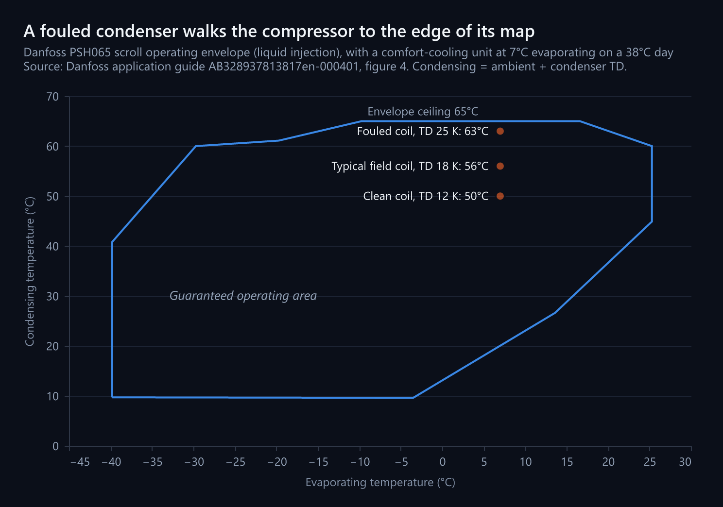
Take a concrete example. Danfoss publishes the application guide for its PSH065 and PSH105 scroll compressors, the sort of machine that sits in commercial chiller and rooftop plant. Its envelope charts run from minus 45 to plus 30 degrees on the evaporating axis and from 0 to 70 degrees on the condensing axis, and the guide states the purpose directly: the envelope "guarantees reliable operation of the compressor for steady-state and transient operation".
Two things follow that are worth being precise about.
First, the envelope is defined by conditions, not by a switch. There is no light that comes on when you leave it. A compressor outside its envelope generally keeps running, which is exactly why the condition persists for years.
Second, the guarantee is conditional in ways the chart does not show on its face. The same guide notes that the steady-state envelope is valid for a suction superheat within a 5 K range at nominal voltage. Change the superheat or the supply voltage and you are no longer reading the chart you think you are reading.
What draws the boundaries
Each edge of the shape is a different physical limit, and knowing which edge you are near tells you what will fail.
The top edge is heat. As condensing temperature rises, the compressor works against a higher pressure, the compression ratio increases, and the gas leaving the compressor gets hotter. The Danfoss guide puts a hard number on it: "In every instance, the discharge temperature must be kept below 135 degrees C." On these compressors, liquid injection is used to hold that line, and the guide specifies that the injection is activated when discharge temperature exceeds 121 degrees C, measured on the surface of the discharge pipe 40 mm from the compressor discharge port.
That measurement point is worth remembering. It is where a technician should be putting a probe, and it is a reading that almost never appears on an Indian service report.
The right edge is motor load. Higher evaporating temperature means denser suction gas, more mass flow, more work, more current. Past a point the motor is the constraint, not the thermodynamics.
The left and bottom edges are lubrication and motor cooling. At very low evaporating temperature the suction gas is thin. Thin gas carries less oil back and removes less heat from the motor windings, so the machine can overheat while the refrigerant around it is extremely cold.
The failure mode at every one of those edges is the same in the end: the oil stops being oil. Refrigeration lubricant is a chemical with a service temperature, and heat is what ages it.
Kerala pushes the top edge, and the condenser decides how hard
Condensing temperature is not a setting. On an air-cooled system it is ambient air temperature plus the temperature difference the condenser needs to reject its heat. Write it as:
Condensing temperature = ambient dry bulb + condenser TD
The TD is partly a design decision, since more coil surface buys a tighter TD at a higher capital cost, and partly a maintenance outcome, because a fouled or airflow-restricted coil has to run a bigger TD to shift the same heat.
The arithmetic is unforgiving. The table below simply adds the two numbers, using three TD bands: a well-selected clean coil, a typical field condition, and a coil that is dirty or short of air.
| Ambient | TD 12 K, clean and well-selected | TD 18 K, typical field condition | TD 25 K, fouled or airflow-starved |
|---|---|---|---|
| 30 degrees C | 42 | 48 | 55 |
| 33 degrees C | 45 | 51 | 58 |
| 35 degrees C | 47 | 53 | 60 |
| 38 degrees C | 50 | 56 | 63 |
Read the right-hand column against that Danfoss chart. Its axis runs to 70 degrees, but the guaranteed area does not: on the PSH065 liquid-injection envelope the ceiling is 65 degrees condensing, sloping down to 60 degrees at the warmest evaporating temperatures. A comfort-cooling unit evaporates at around 7 degrees, where the ceiling is 65. A machine at 63 degrees condensing is two degrees from the edge of its map, and it got there through maintenance rather than through selection. Nobody changed the equipment. The coil got dirty.
The mechanisms that inflate TD in this state are consistent enough to list:
- Salt and dust loading on the fins, which in coastal Kozhikode, Kochi and Kannur is a continuous process rather than a seasonal one
- Outdoor units in service shafts, parapets and light wells that recirculate their own discharge air, so the coil is breathing air several degrees hotter than the shade temperature outside
- Insufficient clearance behind or above a unit, the single most common installation shortcut and one we have written about in the installation shortcuts that cost the most later
- Condenser fans running down or one fan out on a multi-fan condenser, which halves the airflow while the unit continues to hold setpoint
- Non-condensable gases in the circuit from a poor evacuation, which occupy condenser volume and raise head pressure
That last one links back to moisture. The same Danfoss guide is explicit that excessive air and moisture can increase condensing pressure and cause high discharge temperatures, can create acid giving rise to copper plating, and can destroy the lubricating properties of the oil. It sets the target band too: the compressor is delivered below 100 ppm moisture, may be up to 100 ppm at commissioning, and the filter drier must bring the operating level down to between 20 and 50 ppm.
Superheat is the other half of the discharge temperature
Condensing temperature is only one input to how hot the gas gets. The other is what the refrigerant looked like when it arrived at the compressor.
The Danfoss guide sets the range plainly: in any conditions, the expansion device must ensure a suction superheat within 5 to 30 K.
Both ends of that range are a failure.
Too little superheat means liquid refrigerant is reaching the compressor. It dilutes the oil, it washes the bearings, and on a scroll it can do immediate mechanical damage. The guide has a whole procedure around detecting flood-back, and defines oil superheat as oil temperature minus evaporating temperature, which is the practical way to see dilution happening.
Too much superheat means the evaporator is starved. The gas arriving at the compressor is already hot before any compression happens, so it leaves hotter still, and the discharge temperature climbs towards that 135 degree line from a running start.
This is the loop behind a pattern many owners will recognise. A system loses a little charge. Superheat rises. Discharge temperature rises. The oil ages faster. Cooling gets weaker, so someone tops up the gas without finding the leak, and the cycle repeats with the compressor a little more tired each time. The correct response is to find the leak, which is what thermal imaging and electronic detection are for, and to check whether the system is genuinely undercharged or badly tuned.
Why the star rating on the box does not describe a Kerala afternoon
There is a related point worth making, because it explains a gap between expected and actual running cost that owners often blame on the equipment.
India rates air conditioner efficiency with ISEER, a seasonal figure, and the Bureau of Energy Efficiency defines exactly how it is computed. Its schedule for light commercial air conditioners states that the evaluation is based on a bin temperature range of 24 to 43 degrees C and 1600 operating hours of cooling per annum, and it publishes the reference outdoor temperature bin distribution as a table.
That distribution is worth looking at closely:
| Outdoor temperature band | Hours in the BEE reference year | Share of 1600 hours |
|---|---|---|
| 24 to 28 degrees C | 836 | 52.3 per cent |
| 29 to 32 degrees C | 465 | 29.1 per cent |
| 33 to 37 degrees C | 231 | 14.4 per cent |
| 38 to 43 degrees C | 68 | 4.3 per cent |
More than half of the reference year sits at or below 28 degrees outdoors, and only 178 of the 1600 hours are at 35 degrees or above.
This is one national reference profile applied to the whole country, which is a reasonable way to build a comparable label and a poor way to predict what a specific building in Kerala will do. A coastal Kerala installation does not get the long cool shoulder that the low bins represent, and it runs its hours against high humidity, which loads the latent side of the coil in a way a dry-bulb bin table does not capture at all. We covered that split in dry bulb temperature and relative humidity in Kerala HVAC.
The label is not wrong and it is not a marketing trick. It is a comparison tool, and it compares two machines honestly. It simply is not a forecast of your electricity bill, which is the job of an actual energy audit on the building you own.
What the safety devices do and do not tell you
A common assumption is that if the high pressure switch has not tripped, the system must be fine. It is worth being clear about what those devices are for.
The Danfoss guide's instruction is unambiguous: low pressure and high pressure safety switches must never be bypassed nor delayed, and must stop all the compressors. The high pressure switch must be reset manually. Low pressure auto restart must be limited to five times within twelve hours. On the PSH065 and PSH105 there is also an integrated discharge gas temperature protection, and excessive discharge temperature trips the electronic module output relay.
Those are the last line, not the operating range. A safety switch is set outside the envelope, not at its edge, so a machine can sit outside its guaranteed map indefinitely without ever giving a safety a reason to act. The manual reset requirement on the HP switch exists precisely because a high pressure trip is meant to bring a human to the machine rather than let it cycle its way through the problem.
If a system is tripping on high pressure repeatedly and being reset repeatedly, that is not a nuisance trip. It is a machine that has been outside its envelope for a long time and has finally gone far enough to say so.
What we measure, and what it tells us
None of the above needs exotic instruments. It needs the readings actually being taken and written down, which is the difference between a maintenance visit and a filter clean.
| Reading | Where it comes from | What it tells you |
|---|---|---|
| Saturated suction temperature | Low side pressure | Position on the horizontal axis of the envelope |
| Saturated condensing temperature | High side pressure | Position on the vertical axis, the one Kerala pushes |
| Ambient dry bulb at the condenser inlet | At the coil face, not the weather report | Whether the unit is breathing its own discharge air |
| Condenser TD | Condensing temperature minus inlet air | The clearest single number for coil and airflow condition |
| Discharge line temperature | Discharge pipe surface, 40 mm from the port | Distance from the 135 degree limit |
| Suction superheat | Suction pressure and line temperature | Whether the metering device is in the 5 to 30 K band |
| Subcooling | High side pressure and liquid line temperature | Charge condition and condenser performance |
| Running current per phase | Clamp meter against nameplate maximum | Motor loading and supply quality |
Trend matters more than any single visit. A condenser TD that has moved from 14 to 21 K over three visits is a coil telling you what it is going to do next summer, and it is visible a full season before the first complaint. That is the actual argument for a planned contract rather than breakdown calling, which we set out in what an AMC service lifecycle covers.
For commissioning, the same guide asks for the system to be monitored for a minimum of 60 minutes after initial start-up, checking correct superheat and subcooling, current draw within acceptable values, absence of abnormal vibration and noise, and correct oil level. An hour of watching a new machine is cheap. Most of the systems we later find running outside their envelope never got that hour.
What an owner can check without instruments
Four things, all visible, none requiring gauges.
- Look at the condenser coil. If you cannot see daylight through the fins, the TD is already elevated. In coastal locations this needs checking more often than most contracts assume.
- Look at what is around the outdoor unit. Measure the clearance behind and above it. If the unit is in a shaft, a duct enclosure or a boxed-in balcony, ask specifically whether it is recirculating its own hot air.
- Count the fans that are turning. On multi-fan condensers, one stopped fan is easy to miss and roughly doubles the load on the remaining airflow path.
- Ask your contractor for the readings, not the report. Condensing temperature, condenser TD, superheat, subcooling and running current. If those five numbers are not recorded anywhere, nobody knows whether your compressor is inside its envelope, and the first evidence will be a failure.
The envelope is a promise with conditions attached. Kerala's ambient and coastal fouling attack exactly the condition that matters most, quietly, over years, on machines that are still cooling well enough that nobody investigates. Measuring it is not difficult. It is only a question of whether anyone is doing it before the compressor answers the question itself.
If you want those five readings taken and trended on your own plant rather than assumed, that is what our annual maintenance contracts are built around. Contact our team for a site assessment.
Why this matters to you
Where HRS fits after the first breakdown is avoided
Routine maintenance matters most before the first serious breakdown. HRS uses AMC planning, filter and coil servicing, and proper fault diagnosis to keep comfort systems from slipping into high-power, low-performance operation.
Related Service
Annual Maintenance Contracts (AMC)Related Guides
Continue your research
These guides cover the next decisions commonly connected to this topic.
Keep Exploring
Continue from this guide into the matching HRS service page or a relevant Kerala service area.
Related Services
Need expert HVAC help?
Contact our team for professional installation, maintenance, or a custom consultation.