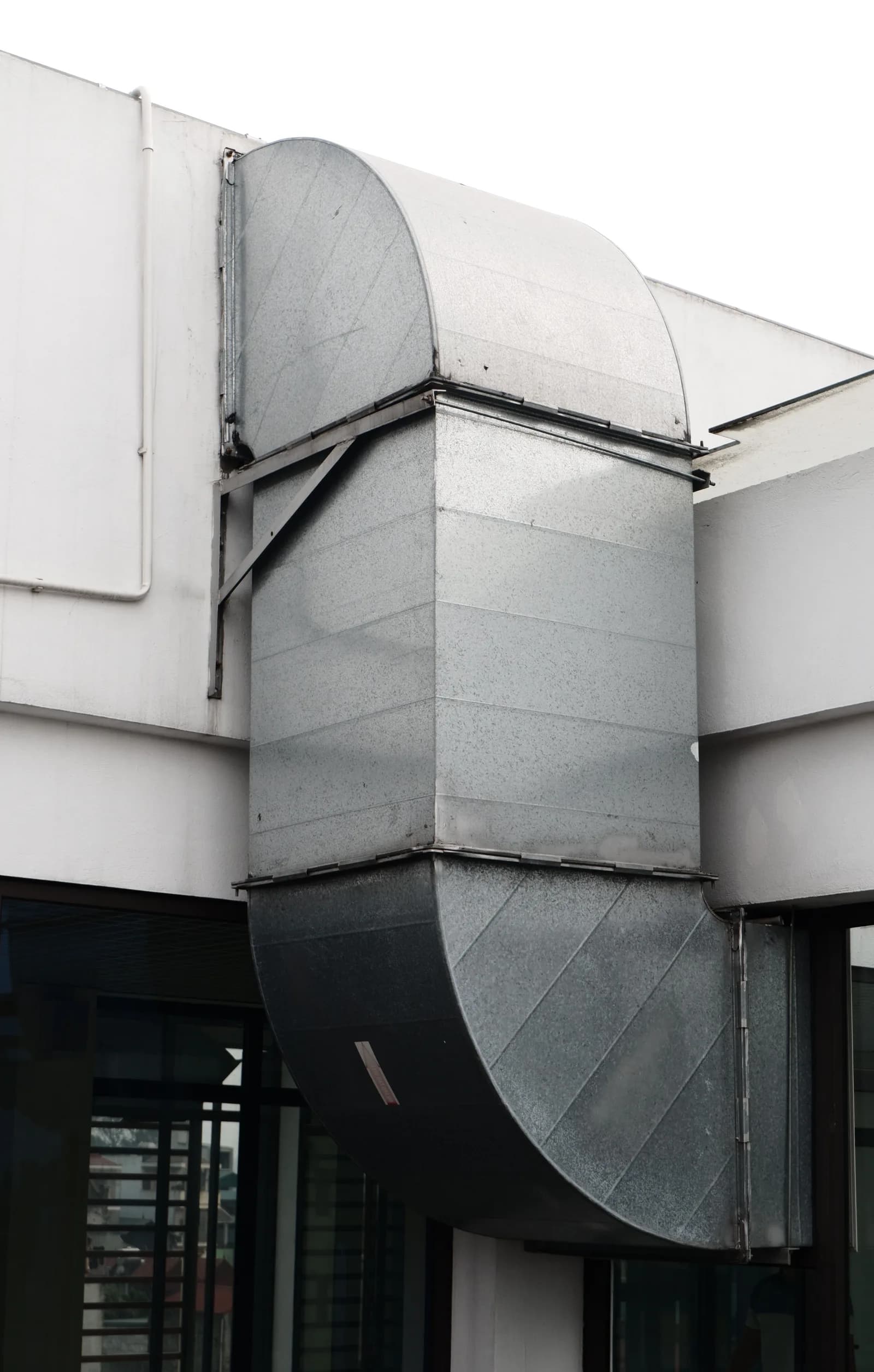
Almost every ducting argument on a Kerala site eventually narrows to one question: 22 gauge or 24 gauge. It is the wrong question asked in the right area. Sheet thickness matters, but it is not a preference, and it is not a proxy for quality. It is a number the duct's own size and pressure class determine for you.
What the gauge conversation is really groping towards is a set of harder questions. Will this duct rumble? Will it sweat in a Kerala ceiling void? Will the joints still be tight in five years, or will the fan slowly shake them open? Those questions have answers, and most of them are written down in standards that are freely readable.
This piece is for consultants, builders, facility teams and owners who want to specify ducting properly rather than argue about a gauge number.
Gauge is a trade label. The standard speaks in millimetres
In Indian ducting practice, "24 gauge" and "22 gauge" are shop-floor shorthand for roughly 0.6 mm and 0.8 mm of galvanised sheet. They are not the same thing as the US galvanised sheet gauge table, where 24 gauge is nearer 0.70 mm and 22 gauge nearer 0.85 mm. Two fabricators can both honestly say "22 gauge" and hand you sheet that differs by 0.05 mm.
IS 655 : 2006, Air Ducts - Specification, the Indian Standard that governs this work, does not use gauge numbers at all. It specifies a minimum thickness in millimetres, chosen against the duct's long side and its pressure class (Table 4):
| Long side of duct | Low pressure (up to +500 Pa) | Medium and high pressure | Minimum thickness |
|---|---|---|---|
| up to 450 mm | applies | not permitted | 0.5 mm |
| 450 to 750 mm | applies | not permitted | 0.6 mm |
| 750 to 1500 mm | applies | up to 450 mm | 0.8 mm |
| 1500 to 2200 mm | applies | 450 to 1200 mm | 1.0 mm |
| above 2200 mm | applies | above 1200 mm | 1.2 mm |
Two things fall out of that table immediately.
First, the same duct size takes a heavier sheet as soon as the pressure class rises. A 400 mm duct is 0.5 mm sheet on a low-pressure system and 0.8 mm on a medium-pressure one. IS 655 sets low pressure at up to +500 Pa, medium at +500 to +1000 Pa and high at +1000 to +2500 Pa. Nobody can tell you the right gauge without knowing the static pressure the system runs at.
Second, "22 gauge everywhere" is not a premium specification, it is an unpriced one. On a mixed job the mains genuinely need 0.8 mm and the branches genuinely do not, and running 0.8 mm through the branches buys you weight rather than performance.
What the extra weight actually costs
Galvanised steel is about 7,850 kg per cubic metre, so 0.6 mm sheet weighs roughly 4.7 kg/m² and 0.8 mm roughly 6.3 kg/m², a third heavier.
Take a 600 x 400 duct. Its perimeter is 2 m, so every running metre uses about 2 m² of sheet. That is roughly 9.4 kg per metre at 0.6 mm against 12.6 kg per metre at 0.8 mm. Over a 30 m run, the heavier sheet adds about 95 kg to what the false ceiling and the hangers have to carry, before insulation, flanges and dampers. On a large project that is real steel, real hanger sizing and real money, and it does nothing for you if the duct was already correctly specified.
The reverse error is worse. A duct built one bracket lighter than IS 655 asks for does not fail dramatically. It flexes, and flexing is where the rest of this article begins.
Zinc matters more than gauge in a coastal state
Base steel thickness gets all the attention. Coating thickness is what decides how the duct ages in Kerala.
IS 655 requires the galvanised sheet to conform to IS 277, and asks for a heavier coating on outdoor uninsulated duct than on indoor or insulated duct. IS 277 grades zinc by total coating mass across both faces, from 120 g/m² up to 600 g/m², and its own recommendation for sheet in the 0.63 to 1.0 mm band, which is exactly the ducting range, is grade 275.
At 275 g/m², the zinc layer is about 19 microns per face. That is the entire corrosion budget of the duct. In coastal Kozhikode or Kochi air, with chloride in the breeze and a ceiling void that runs humid for eight months of the year, a sheet supplied at 120 g/m² has spent less than half that budget before the duct is even hung.
There is a practical consequence people miss when they micrometer sheet on site. A vernier reading includes the zinc. Nominal 0.8 mm sheet carrying a 275 g/m² coating measures around 0.84 mm in total, so a sheet that measures 0.80 mm dead may be 0.76 mm of steel with a good coating, or 0.79 mm of steel with almost no coating. Thickness alone cannot tell you which. Only the mill test certificate can.
Zinc also fails first where it has been cut. Sheared edges, rivet holes, screw penetrations and drilled flanges are all raw steel. Specify a zinc-rich touch-up on cut edges as part of the fabrication method, not as a remedial item after the first rust bloom appears.
Why HRS specifies JSW or Tata Steel sheet for Kerala work
This is not brand loyalty, and it is not a claim that no other mill can make good sheet. It is about what arrives with the coil.
Sheet from a primary Indian mill, JSW Steel or Tata Steel in our case, comes with a mill test certificate that states the base metal thickness and the zinc coating mass, and it comes from a coil whose thickness holds across its width. Secondary and re-rolled material often does not. The common failures are consistent enough to predict: sheet sold as 0.8 mm that measures 0.72 mm, a declared coating that a lab test cannot find, and coil-to-coil variation that shows up as ripple in the finished panel and a seam that will not close cleanly.
The cost difference between certified mill sheet and the alternative is a small fraction of a ducting package. The cost of re-fabricating a rumbling, sweating duct run above a finished ceiling is not.
If you are specifying the work yourself, three checks catch most of it:
- Ask for the mill test certificate against the coil, and check that the coating grade on it is the one your specification asked for.
- Micrometer the sheet at four points across the width, not one, and read it as base plus coating.
- Check the coil marking physically rather than accepting a verbal assurance about origin.
We have written more broadly about where these specification gaps open up in the HVAC mistakes that show up on builder-led projects and in HVAC coordination for MEP contractors.
Duct noise is three different problems
"The ducting is noisy" is a symptom with at least three unrelated causes, and treating the wrong one is why so much money gets spent on insulation that changes nothing.
1. Fan noise carried in the air stream
The fan makes sound, and the duct is a very efficient pipe for it. This is the noise that arrives out of the diffuser along with the air. It is fixed with attenuators, a lined plenum box before the terminal, lower duct velocity and a straight approach into the terminal. External wrapping does almost nothing to it, because the sound is inside the duct, not radiating through the wall.
2. Breakout noise, or duct rumble
Low-frequency energy makes the flat duct wall vibrate, and the wall radiates it into the ceiling void and down into the room. This is the deep, tiring hum that people describe as "the AC sound" without being able to point at a grille.
This is a stiffness and geometry problem. A flat unstiffened panel is a drum, and a wide flat duct has bigger drums than a squarer one of the same free area. A 1000 x 250 duct and a 600 x 400 duct both give you 0.25 m² of airway. The flat one has a 2.5 m perimeter against 2.0 m, so it uses 25 per cent more sheet and more insulation for the same air, and it presents much larger unbraced panels. IS 655 caps the recommended aspect ratio at 1:4 for exactly this kind of reason, so a 1000 x 250 duct is sitting at the standard's limit rather than comfortably inside it.
IS 655 also carries the fix. Table 26 requires that ducts which are not thermally insulated, with a long side over 450 mm, get a diamond brake or a reinforcement rib at a pitch of no more than 300 mm. Cross-breaking a panel costs a pass on the machine and takes the drum out of it.
3. Regenerated noise
This is noise made by the air itself where the geometry is bad: a balancing damper closed down to 20 per cent, a sharp transition, a tight elbow immediately before a diffuser, an undersized branch fighting for its share. It is the whistle or hiss that appears only when the system is balanced and disappears when a damper is opened.
No insulation fixes regenerated noise. Geometry made it, geometry has to fix it. Our guide to grilles, diffusers and air terminals covers the terminal end of that problem in detail.
What nitrile insulation actually does
Closed-cell nitrile rubber foam, the NBR/PVC elastomeric material sold under several brand names, has become the default on serious Kerala jobs. It is worth being precise about why, because it is often specified for the wrong reason.
The real reason: it is its own vapour barrier
The competing material is glass wool with a foil facing. Glass wool insulates perfectly well. Its problem is that the foil is the vapour barrier, and the foil is a separate layer that has to be perfect. In practice it gets punctured at every hanger, torn at corners, and lapped with tape at every joint.
Closed-cell nitrile is a vapour barrier throughout its thickness, with a water vapour resistance factor typically quoted in the thousands. There is no separate skin to puncture. Cut it, and the cut face is still closed cell.
That distinction decides everything in a Kerala ceiling void. Take a void at 30°C and 80 per cent relative humidity, which is an ordinary rather than extreme condition here, and a duct carrying air at 14°C. The dew point of that void air is about 26.2°C. Every square metre of duct surface below 26.2°C will grow water.
Working that through with a nitrile conductivity of about 0.036 W/m·K and an outer surface film resistance of about 0.12 m²K/W:
| Insulation thickness | Approximate outer surface temperature | Margin over the 26.2°C dew point |
|---|---|---|
| 13 mm | 26.4°C | essentially none |
| 19 mm | 27.3°C | about 1.1°C |
| 25 mm | 27.8°C | about 1.6°C |
That is why we treat 19 mm as the practical starting point for chilled supply ducts in Kerala ceiling voids rather than 13 mm, and go to 25 mm where the void runs hotter or the supply air is colder. The 13 mm case is not wrong on paper, it simply has no margin, and a duct with no margin sweats the first time the void gets warmer or the supply air gets colder than the design assumed.
Two caveats the table cannot show. The calculation assumes the insulation is in full contact with the duct: an unbonded wrap with an air gap behind it does not behave the way the table says. And a bare metal hanger strap in contact with the duct is a cold bridge that will drip regardless of how thick the flat surfaces are, which is why hanger saddles and continued insulation over the hanger belong in the specification.
For the psychrometrics underneath all of this, see our companion pieces on dry bulb temperature and relative humidity in HVAC calculations and why humidity is Kerala's real HVAC problem.
The acoustic reason: damping, not blocking
Nitrile is also sold on noise, and here the claim needs trimming. Elastomeric foam is light. It adds almost no mass, and mass is what blocks sound. It will not turn a rumbling duct quiet.
What it does do, when it is fully bonded to the sheet rather than loosely wrapped, is damp the panel. A bonded elastomeric layer converts panel vibration into heat and takes the ring out of the metal. That is genuinely useful for the tinny higher-frequency rattle, and it is exactly why a nitrile acoustic collar at the duct-to-terminal connection works: it interrupts vibration transfer at the point where the terminal is closest to the occupant's ear.
Put plainly: nitrile damps, and it stops condensation. It does not attenuate sound travelling inside the duct. When a room genuinely needs in-duct attenuation, the answer is a lined plenum or an attenuator, not a thicker external wrap.
IS 655 recognises the material family directly. Clause 5.2.14 lists nitrile rubber among the permitted sealing materials for seams at duct corners, alongside silicone, butyl and chloroprene.
Vibration, resonance and the slow opening of duct joints
This is the failure mode almost nobody designs against, and the one that quietly costs the most.
Where the "constructive interference" intuition is right, and where it is not
Two different physical effects get grouped under that heading, and both are real.
Standing waves in the air column. A duct is a tube. Sound travelling down it reflects at terminations, plenums and closed dampers, and the reflected wave adds to the incoming one. At frequencies where the section length is a multiple of half a wavelength, pressure peaks park at fixed positions along the run and stay there. With supply air near 14°C, sound travels at roughly 339 m/s, so a 6 m section between two reflecting ends has its fundamental axial resonance near 28 Hz, with further modes stacked above it. This is why a rumble sometimes appears in exactly one room, at exactly one fan speed, and cannot be found anywhere else.
Panel resonance. Each unbraced duct panel has its own natural frequencies. Fan blade-pass frequency is easy to calculate: a fan turning at 900 rpm with nine blades produces a strong tone at 135 Hz. When a forcing frequency lands near a panel mode, the amplitude builds, the same way a swing builds when it is pushed in time. The frequencies do not have to coincide exactly for the response to grow noticeably.
So the intuition is sound. What it usually gets wrong is where the damage lands.
The damage is at the restraints, not in the middle of the panel
The panel is what moves. The transverse joint, the flange, the cleat, the rivet, the screw and the hanger are what do not. Every cycle of panel flexing concentrates strain at those discontinuities, and that is a fatigue mechanism rather than an overload one. Fatigue does not need a large force. It needs a moderate force repeated a very large number of times, and a fan running through a Kerala summer supplies that generously.
Fatigue also concentrates at stress raisers: rivet holes, corner notches, the end of a stiffener where the stiffness changes abruptly, and the sealant line itself.
The symptoms arrive in a recognisable order:
- A buzz or rattle that appears at one fan speed and vanishes either side of it.
- Sealant crazing along seams, visible only if someone goes into the ceiling and looks.
- Gasket extrusion at flanges, and dirt streaking that marks where air has been escaping.
- Rivets and flange bolts loosening.
- Airflow at the far terminals dropping while the fan runs at the same speed and draws the same power.
- In a coastal ceiling void, corrosion starting at exactly those leak points, because escaping cold air condenses on whatever it touches.
The energy cost of stage 5 is not marginal. In a field study of large commercial buildings, Fisk and colleagues at Lawrence Berkeley National Laboratory measured duct air leakage ranging from 0 to 30 per cent of inlet airflow, with most measurements between 10 and 20 per cent (Energy and Buildings 32:1, 2000). The same study found that heat gain between the cooling coil outlet and the supply registers raised supply air temperature by 0.6°C to 2°C on average, giving a conduction effectiveness between 0.75 and 0.90. In plain terms: 10 to 25 per cent of the cooling the plant produced never reached the room, purely through the duct wall.
A tenth to a quarter of the plant's output, lost in the distribution. That is the number that should end the gauge argument and start a joint and insulation argument.
Indian guidance points the same way. The ECBC HVAC tip sheet, published under the USAID ECO-III project and hosted by Kerala's Energy Management Centre, sets the air distribution system at 0.60 kW per ton of cooling in conventional design against 0.06 kW/ton optimised. That is a 90 per cent improvement potential, the largest of any component in the plant and a bigger absolute saving than the chiller. The same document notes that continuously running air distribution fans can consume more electricity over a year than chillers or boilers, which run only intermittently, and that fan and drive mechanical efficiency in the field commonly sits at 40 to 60 per cent where the mid-80s is achievable.
The construction details that prevent it
IS 655 is unusually specific here, and the numbers reward reading.
Reinforcement spacing (Table 23, low pressure, lateral reinforcement):
| Long side of duct | Minimum steel angle | Maximum spacing |
|---|---|---|
| 250 to 750 mm | 25 x 25 x 3 | 1,840 mm |
| 750 to 1500 mm | 30 x 30 x 3 | 925 mm |
| 1500 to 2200 mm | 40 x 40 x 3 | 925 mm |
| above 2200 mm | 40 x 40 x 5 | 925 mm plus tie rod |
For medium and high pressure duct, Table 25 pulls that spacing to 925 mm from 250 mm upward. The stiffener interval halves as soon as the pressure class rises, for the same reason the sheet gets thicker.
Transverse joint spacing (Table 11, low pressure, angle flange technique) allows up to 3,640 mm between joints on ducts under 750 mm, 2,730 mm from 750 to 1500 mm, and 1,820 mm above that. Table 12 brings medium pressure duct to 1,820 mm across every size.
Beyond the standard, the details that decide whether a duct ages well are mostly at the machine:
- A flexible canvas connector at the fan discharge and return, fitted with slack in it. Pulled drum-tight it transmits vibration instead of interrupting it, which is the single most common installation error we are called in to correct.
- Anti-vibration hangers or rubber-lined clamps for the first few metres away from the machine, where structure-borne energy is highest.
- Cross-breaking or beading on large flat panels, at the 300 mm pitch above.
- A sensible aspect ratio. Squarer duct is quieter, uses less sheet and less insulation, and is easier to seal.
- Sealant at the joints, not tape alone. Tape is a finish. It is not a seal, and in a hot void its adhesive is on a clock.
- Nitrile acoustic collar dampening at the duct-to-terminal connection wherever the terminal serves a quiet room.
How to actually test for it
The useful answer to "is this duct going to shake itself loose" is a measurement, not an opinion.
Run a fan speed sweep. Step the fan through its speed range and note where the rumble appears and disappears. A noise that peaks over a narrow band and vanishes either side is a resonance, and a resonance can be moved by stiffening a panel or shifting a joint. A noise that simply rises with speed is a velocity problem, and needs a different fix entirely.
Pressure test the ducts for leakage before the ceiling closes. Pressurise each section to its design class and measure the leakage rate. IS 655 handles this through seal classes N, A, B and C applied by position rather than a single leakage figure, so the specification has to name the class. This is the only number that proves the joints are actually sealed, and it costs a fraction of what it costs to chase a leak above a finished gypsum ceiling.
Record that leakage figure as a baseline, then repeat the test after a full season of running. A rise in leakage at the same test pressure, with nothing else changed, is joint fatigue measured directly rather than argued about. Very few projects in India do this. The ones that do stop having the argument.
Measure vibration velocity at the fan and at the first hanger. If the hanger reading is close to the fan reading, the isolation and the flexible connector are not doing their job, whatever they look like.
Re-torque flange fixings after the first few weeks of operation. Gaskets bed in, and a joint that was tight at handover often is not tight a month later.
Walk the run with a smoke pencil or a thermal camera while the system runs. Leaks show up as cold streaks against a warm ceiling void, and they show up long before anyone in the room notices anything.
What we specify, and why
For ducting work across Kerala, HRS specifies:
- Galvanised sheet from a primary Indian mill, JSW Steel or Tata Steel in our case, supplied against a mill test certificate that states base thickness and zinc coating mass.
- Sheet thickness selected per IS 655 against duct size and the system's actual pressure class, which means different gauges in different parts of the same job rather than one number across the drawing.
- A zinc coating grade chosen for coastal service rather than the cheapest grade that still carries the name galvanised.
- Closed-cell nitrile insulation, fully bonded, with sealed butt joints and seams, at a thickness checked against the actual void condition rather than a default 13 mm.
- Nitrile acoustic collar dampening at duct-to-terminal and ductable connections where the room is noise-sensitive.
- Reinforcement and joint spacing per IS 655 for the pressure class, with cross-breaking on large flat panels.
- Leakage testing before the ceiling closes, with the result recorded so it can be compared later.
None of this is exotic. All of it is ordinary competent practice, written into a standard that has been public since 2006. The reason it is worth stating explicitly is that the duct is the one part of an HVAC system that becomes permanently inaccessible on handover day, and it is the part most often value-engineered by people who will never have to open the ceiling again.
For a systems-level view of how ducting fits into a larger plant, see our walkthrough of multi-zone commercial HVAC design.
Planning a project where the ducting has to be quiet, dry and still tight in five years? Hitech Refrigeration Services (HRS) fabricates and installs custom ducting and ventilation systems across Kerala, with ISO 9001:2015 and ISO 45001:2018 certified processes. We specify sheet, coating grade, insulation thickness and joint detail against the standard and the site condition, and we test the result before it disappears behind a ceiling. Request a quote, contact our team, or read more about custom ducting, fabrication and ventilation systems.
Sources
- IS 655 : 2006, Air Ducts - Specification, Bureau of Indian Standards. Sheet thickness (Table 4), pressure classification (Table 1), aspect ratio (Table 2), joint materials and spacing (Tables 11 and 12), reinforcement (Tables 23 to 26), sealing materials (Clause 5.2.14), seal classes (Clause 9).
- IS 277 : 2003, Galvanized Steel Sheets (Plain and Corrugated), Bureau of Indian Standards. Zinc coating grades and the recommended grade by sheet thickness (Clause 7.3 and Table 2).
- ECBC Tip Sheet: HVAC System, Version 1.0 (reprinted June 2009), USAID ECO-III Project / International Resources Group, hosted by the Energy Management Centre, Government of Kerala. Energy saving potential in HVAC system design (Table 1), air distribution fan energy, and duct system pressure losses.
- Fisk, W.J. and colleagues, Duct systems in large commercial buildings: physical characterization, air leakage and heat conduction gains, Energy and Buildings 32(1), 2000, Lawrence Berkeley National Laboratory.